Sunday, October 14, 2012

MERC OM 906LA


Right after we got the
 valve cover off. 
Wrestling fuel lines.  Each injector
had it's own separate high
pressure pump.
Block with head, oil pan, oil pump,
turbo, and exhaust manifold
removed.


The last couple of weeks have been really exciting for me.  I dove headfirst into engines with a couple of the other guys.  Interestingly enough, we chose the MBE 900 out of the storage garage.  I tried my best to follow the service manual as we dis-assembled the engine.  I made a point of looking at each component and piece we took out to look for wear or even figure out how something worked, so it took us a couple of days for tear down.
Once we got it taken apart, parts organized, and cleaned parts and surfaces I started taking a bunch of different measurements.  Those included a ton of stuff that I've always wanted to know how to do properly.  I learned to use the dial-bore gauge efficiently, as well as a lot of measurements using the micrometers.  Some of the measuring tools we used required a bit of figuring out how to use them as we went; so it was both fun and challenging to figure out different ways to skin a cat.
Quite the difference in
 torque to yield bolts.
Before and after.
Top of head.  Note the 3 valves.
2 intake and 1 exhaust. 
Looking at the bottom side of the engine
at the crankshaft.  Very cool,


GOTTA keep those bolts and parts
clean and organized!

A bit of fun on the side:  changed out my wheel bearings on my Ranger last week as well.  It was a good thing to revisit what I had learned from spring quarter.

Total for Engine Weeks: 62
Total for Fall 2012:        119


Monday, October 1, 2012

Schematics/Diagrams

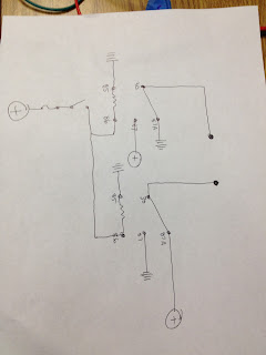
Wiring diagram of our reverse polarity circuit


12v supply fused, 2 relays, a door lock, and a SPST switch


Last week was another interesting week in relays and electrical fun.  Jared and I wanted to find a way to reverse polarity using a SPST switch and two relays.  The diagram we came up with looked to be the most simple way of accomplishing this goal... and it worked!  As a sidenote, because we were using a door lock mechanism we had to very quick as we flipped the switch back and forth.  There were a few burned up fuses before we finished :)
  The light boards continued to give me quite a headache throughout the week.  I realized that the way that I had the light boards set up worked, but were not wired in exactly as the schematic shows.  The headlights, in particular, were shown on the schematic as being a ground control circuit.  In the picture below, the headlights have switched power coming from the headlamp switch that supplies power to the contacts of the relay (both high and low beam relay, or 87 and 87a on the relay).  When the high beam push button switch is pushed, the relay coil energizes and moves the contacts over.  What is different than what I thought is that the ground (blue wire in diagram) is connected from the ground side of the relay coil to the previously thought 'always power', or 30 on the relay.  This means that the headlights are not grounded directly, but have the 'control' on the ground side of the load.
  I was really happy to be able to learn a different way of wiring something as simple as a headlight and switch.  If I am working on a truck and think I know the way it is wired, I could potentially wire it wrong.  This would cause more headaches than I ever need in electrical troubleshooting.  This could be the most invaluable thing I've learned so far:  learn to read your diagrams/schematics.  I may know how to wire that particular board by heart, but as I go on in my career I am destined to see a lot I don't actually know how it works.  Reading plans is priceless.

Wiring diagram of High/Low Beam circuit


Week 2 hrs: 32
Total:  56