Tuesday, April 2, 2013
SPQ13 Tracy
Learned some more great things about why Jeff is having us use the blogs. I've always viewed them as a source of information to come back to when I needed it later in life. Come to find out they are used primarily as a means of cementing what we are learning in class. I now view my blog as a more immediate benefit and can see myself using it much more often.

Monday, January 14, 2013
Winter Qtr starts again
Not a lot of hours in the shop so far, and wont be for the rest of this quarter due to extra general ed classes I'll be taking, but I do have a little bit that I've picked up so far. BTC's Yale forklift was burning coolant and poofing out loads of smoke, so I finally got the head off today. I want to do some more research in regards to what kind of unique wear that propane has over gas. I did figure out that it has a very similar engine to a 1988 mazda b2200 2.2L FE (still haven't found the engine tag). Also put a little time into seeing how a propane system works, and it is pretty much the same as gas. A little conversion kit is all it took, and it burns the gas like any other fuel. Boom! and the crank goes round. Pretty basic, but I wanted to make sure before I tore into it. I'll get some pics of the gasket and head damage after I do that propane damage research.
Total hours must be around: 18
Sunday, November 25, 2012
Disassembly is the easy part
I checked and adjusted the Cummins ISX valves in the dyno room, including engine brake exhaust valve and the injector. Injector only requires a torque value, while the valves all required setting to clearance and then torquing. The engine brake took some figuring out. I know now howto set the rail for the neutral detent position, as well as setting the set screw for 7mm movement. I had to use a magnetic base dial indicator since I did not have a 7mm feeler gauge. After set, I scanned the ECM for codes.


By far the most important thing that I've learned over this engine section of the quarter is how important cleanliness is while working. Worked on the 16 cylinder cat engine set up at school. Got the head off, piston pulled, and liner removed and spent a good deal of time cleaning.


I hooked up the Modis to my pickup because it was idling high, and then when the engine speed dropped the engine felt like it was misfiring quite a bit. Also have quite a high pitched noise that goes away, or at least diminishes significantly, with throttle applied. KOER tests showed misfire counts progressively going up at around 2 per second. The long term fuel trim (LTFT) reading on bank 2 was reading a value of 10 during low idle, and would drop to around 3 with throttle. short term fuel trim (STFT) readings were good for both banks, at close to 1. The values for bank 1 LTFT were also close to 1 consistently.
"LTFT Adaptation Valve Positive (+) LTFT>1: A) Lack of fuel or too much air, ECU is attempting to increase the amount of fuel by increasing the injector open time and/or B) could be caused by unmetered air leaking past the EVAP, EGR, or into the air intake system after the Air Mass Meter (MAF) or a fuel pump delivery problem or clogged or damaged fuel injector."
Set up a compression test for cyliners 1-6 respectively (psi): 183, 171, 171, 175, 180, 177. I seem to remember that alldata has information stating that I should really be concerned if I have a low range of around 125 if my highest reading is 175. Spark plug gaps should be 0.042-0.044 in, ended up being: 0.054, 0.056, 0.054, 0.050, 0.075, 0.054. Plugs on cylinders 2,3, and 5 had heavy amounts of wet oil and cylinder 5 had a large amount of caked on... gunk (?). Picked up another gasket set and head bolts and set about doing the job right.
I scrubbed away at the vibration damper to find the ever elusive timing marks. From there, I took a page from something Raul told me about and I measured around the circumference (18 in), then divided by 3 to get marks every 120*. Knowing the firing order, I know which piston is at TDC for each mark. I spent an easy 12 hours cleaning and chasing threads over the weekend, as well as found that at least 2 of my valve stem seals were torn or the compression spring had failed. Both rubber gaskets between the lower intake manifold and block were shredded as well as both gaskets between lower intake manifold and cylinder head were torn. I attribute those rapid failures to my lack of preparation and cleanliness of mating surfaces. I am also hoping that the valve train noise under load, as mentioned in previous posts, will be resolved. I figure that because I did not chase the rocker arm fulcrum bolt holes my torque values are not even close to accurate, which could, from what I'm thinking, cause the rockers to be looser than tolerance. I'm hoping.


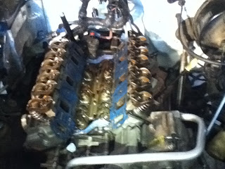


By far the most important thing that I've learned over this engine section of the quarter is how important cleanliness is while working. Worked on the 16 cylinder cat engine set up at school. Got the head off, piston pulled, and liner removed and spent a good deal of time cleaning.


I hooked up the Modis to my pickup because it was idling high, and then when the engine speed dropped the engine felt like it was misfiring quite a bit. Also have quite a high pitched noise that goes away, or at least diminishes significantly, with throttle applied. KOER tests showed misfire counts progressively going up at around 2 per second. The long term fuel trim (LTFT) reading on bank 2 was reading a value of 10 during low idle, and would drop to around 3 with throttle. short term fuel trim (STFT) readings were good for both banks, at close to 1. The values for bank 1 LTFT were also close to 1 consistently.
"LTFT Adaptation Valve Positive (+) LTFT>1: A) Lack of fuel or too much air, ECU is attempting to increase the amount of fuel by increasing the injector open time and/or B) could be caused by unmetered air leaking past the EVAP, EGR, or into the air intake system after the Air Mass Meter (MAF) or a fuel pump delivery problem or clogged or damaged fuel injector."
Set up a compression test for cyliners 1-6 respectively (psi): 183, 171, 171, 175, 180, 177. I seem to remember that alldata has information stating that I should really be concerned if I have a low range of around 125 if my highest reading is 175. Spark plug gaps should be 0.042-0.044 in, ended up being: 0.054, 0.056, 0.054, 0.050, 0.075, 0.054. Plugs on cylinders 2,3, and 5 had heavy amounts of wet oil and cylinder 5 had a large amount of caked on... gunk (?). Picked up another gasket set and head bolts and set about doing the job right.
I scrubbed away at the vibration damper to find the ever elusive timing marks. From there, I took a page from something Raul told me about and I measured around the circumference (18 in), then divided by 3 to get marks every 120*. Knowing the firing order, I know which piston is at TDC for each mark. I spent an easy 12 hours cleaning and chasing threads over the weekend, as well as found that at least 2 of my valve stem seals were torn or the compression spring had failed. Both rubber gaskets between the lower intake manifold and block were shredded as well as both gaskets between lower intake manifold and cylinder head were torn. I attribute those rapid failures to my lack of preparation and cleanliness of mating surfaces. I am also hoping that the valve train noise under load, as mentioned in previous posts, will be resolved. I figure that because I did not chase the rocker arm fulcrum bolt holes my torque values are not even close to accurate, which could, from what I'm thinking, cause the rockers to be looser than tolerance. I'm hoping.


Hours for last 2 weeks: 56
Total Hours: 315
Sunday, November 11, 2012
Modis
Dinkin around with the computers and sensors so far has really put my mind in the right place when it comes to starting a troubleshooting method. It all makes a lot more sense just knowing that the ECM is simply taking measurements from temp/pressure sensors and controlling various things throughout the truck. Found out that that is called bi-directional control. For instance, when I used the Modis on the Dodge to grab the codes for a crank but no start condition, that is called one-directional control. I messed around with the horn and wiper relays to work on the Dodge with the Modis KOEO. That's bi-directional control. When the Modis is receiving information at the same time as it is commanding.
Also, the codes for the Dodge were P0201-P0206 which are 'Cylinder 1 (through 6 respectively) Injector Circuit/Open. Went into All-Data, and there is a troubleshooting list that ended up being 7 steps long. The possibilities for this code are: injector harness open, a hihg or low side driver harness open, or a problem with the ECM. Just the fact that all are throwing a code that all 6 circuits are open tells me that somewhere between the ECM and the injectors there is a cut wire or the harness is unplugged.
 I also got a chance to hook up the Modis to the Freightliner in the shop. Jeff asked us to scan for codes, and I found a couple. Under Engines: DIC 108, FMI 3-Voltage above normal or shorted high, Active PID (YES), Occurance Count (N/A). Under Brakes, Power Unit: FMI 5-current below normal or open, Active SID (YES) and FMI11-current below normal or open, Active SID (YES).
 From there I took the Modis and hooked it up in series with the CamPositionSensor. Got some really great digital waves going on. I dinked with the settings quite a bit. I picked the 2ch 10v preset. Then when it comes up there are multiples lines that are just picking up interference... birds. I turned those off in the lower right corner under ch1-4, leaving only the one channel I was using. Specifically had display inverted, peak detect, and auto-find. Auto-find 'scaled' it down and read it under easy to see voltage and time. I changed it to 20v and 50ms. Also found that with the peak detect on it just barely highlights the spikes of the graph, so I could easily move the trigger to those high spots and the graph would practically freeze in place but still be reading at the same time. These pictures show the odd teeth in the cam that run by the sensor. They are the markers for the ECM to know where TDC is, via the CPS.
Also learned something about the Dodge. That the FCA is a fuel control actuator that works a solenoid valve electronically. It is opened by the ECM based on demanded fuel pressure. It controls the fuel pressure in the HS common rail of the fuel delivery system (23,206 psi).
The dodge also has 2 intake air heater elements, controlled by the ECM, to help heat the air coming into the intake manifold. They help with engine starting and better driveability when it's cold outside. Each element pulls 95A at 12V, or 190A total. Lots of 'juice'.
Worked on my DRZ engine again, cleaning and measuring. Measured everything that the Suzuki service manual showed, and my final assessment is that I need new valves, camshafts, shims, and guides. I will be measuring the guides again when I get new valves, since the way the guides are measured all depends on the size of valve installed. Since my stems were worn down past spec, new valves may keep the guides in spec.


This is off of the Caterpillar Engines folder from Jeff. Lots of great info.
Day 33 DET 202
Hours last week: 42
Total Hours: 259
Also, the codes for the Dodge were P0201-P0206 which are 'Cylinder 1 (through 6 respectively) Injector Circuit/Open. Went into All-Data, and there is a troubleshooting list that ended up being 7 steps long. The possibilities for this code are: injector harness open, a hihg or low side driver harness open, or a problem with the ECM. Just the fact that all are throwing a code that all 6 circuits are open tells me that somewhere between the ECM and the injectors there is a cut wire or the harness is unplugged.
 I also got a chance to hook up the Modis to the Freightliner in the shop. Jeff asked us to scan for codes, and I found a couple. Under Engines: DIC 108, FMI 3-Voltage above normal or shorted high, Active PID (YES), Occurance Count (N/A). Under Brakes, Power Unit: FMI 5-current below normal or open, Active SID (YES) and FMI11-current below normal or open, Active SID (YES).
  From there I took the Modis and hooked it up in series with the CamPositionSensor. Got some really great digital waves going on. I dinked with the settings quite a bit. I picked the 2ch 10v preset. Then when it comes up there are multiples lines that are just picking up interference... birds. I turned those off in the lower right corner under ch1-4, leaving only the one channel I was using. Specifically had display inverted, peak detect, and auto-find. Auto-find 'scaled' it down and read it under easy to see voltage and time. I changed it to 20v and 50ms. Also found that with the peak detect on it just barely highlights the spikes of the graph, so I could easily move the trigger to those high spots and the graph would practically freeze in place but still be reading at the same time. These pictures show the odd teeth in the cam that run by the sensor. They are the markers for the ECM to know where TDC is, via the CPS.
Also learned something about the Dodge. That the FCA is a fuel control actuator that works a solenoid valve electronically. It is opened by the ECM based on demanded fuel pressure. It controls the fuel pressure in the HS common rail of the fuel delivery system (23,206 psi).
The dodge also has 2 intake air heater elements, controlled by the ECM, to help heat the air coming into the intake manifold. They help with engine starting and better driveability when it's cold outside. Each element pulls 95A at 12V, or 190A total. Lots of 'juice'.
Worked on my DRZ engine again, cleaning and measuring. Measured everything that the Suzuki service manual showed, and my final assessment is that I need new valves, camshafts, shims, and guides. I will be measuring the guides again when I get new valves, since the way the guides are measured all depends on the size of valve installed. Since my stems were worn down past spec, new valves may keep the guides in spec.


This is off of the Caterpillar Engines folder from Jeff. Lots of great info.
Day 33 DET 202
Hours last week: 42
Total Hours: 259
Sunday, November 4, 2012
ServiceMaxx and Auto Decompress... oh my!


This is the table the service manual had, with all the numbers mathed out.

 I got real familiar with my drz400 starting Thursday morning, and got so wrapped up I missed the day entirely. What started with simply opening up the valve cover, ended with the engine on my bench. That was soon followed by the the cylinder and head coming off. Cleaned them both of real good and am now waiting for a valve spring compressor. The tops of the valves and springs are seated way down in the head, so I am getting one that is similar to the one at the school. Except, it has a hollow end that encircles the outside top of the valve. That will be cut open to allow me to pull out the keepers and hopefully check the valve measurements. News on that to continue.
'08 DRZ400sm Camshaft Automatic Decompression
Truck was making a metal clatter sound, that I thought was intermittent but found it to be prominent just as it is put under load, and will decrease as engine speed increases. Since I have had trouble with the pos Ford rockers before, I decided to have a look-see. One of the rocker arms on the left bank had more wiggle than the others. I took it off, cleaned it out, and checked the pushtube for straightness. There was more wear on both contact points of the rocker arm than I'd like to have seen, but I was under time constraint. Kind of like being in the wilds of Alaska. I got it back together to proper torque and headed off. All that being said, the noise is still there but not as noticeable. Will be looking into that more.
Did a bunch of stuff on the ServiceMaxx software. I learned more than I could have thought, but know I've barely scratched the surface. The errors are frustrating, but learning to understand what they mean is invaluable. The testing for the KOEO and KOER tests must be in sequence to work. Some of the other testing requires that the user terminate the test to complete it. All things that were stated somewhere in the software, as long as it's found.
Total hours: 217
Hours since last post: 98
Sunday, October 14, 2012
MERC OM 906LA
 |
| Right after we got the valve cover off. |
 |
| Wrestling fuel lines. Each injector had it's own separate high pressure pump. |
 |
| Block with head, oil pan, oil pump, turbo, and exhaust manifold removed. |
The last couple of weeks have been really exciting for me. I dove headfirst into engines with a couple of the other guys. Interestingly enough, we chose the MBE 900 out of the storage garage. I tried my best to follow the service manual as we dis-assembled the engine. I made a point of looking at each component and piece we took out to look for wear or even figure out how something worked, so it took us a couple of days for tear down.
Once we got it taken apart, parts organized, and cleaned parts and surfaces I started taking a bunch of different measurements. Those included a ton of stuff that I've always wanted to know how to do properly. I learned to use the dial-bore gauge efficiently, as well as a lot of measurements using the micrometers. Some of the measuring tools we used required a bit of figuring out how to use them as we went; so it was both fun and challenging to figure out different ways to skin a cat.
A bit of fun on the side: changed out my wheel bearings on my Ranger last week as well. It was a good thing to revisit what I had learned from spring quarter.
 |
| Quite the difference in torque to yield bolts. Before and after. |
 |
| Top of head. Note the 3 valves. 2 intake and 1 exhaust. |
 |
| Looking at the bottom side of the engine at the crankshaft. Very cool, |
 |
| GOTTA keep those bolts and parts clean and organized! |
A bit of fun on the side: changed out my wheel bearings on my Ranger last week as well. It was a good thing to revisit what I had learned from spring quarter.
Total for Engine Weeks: 62
Total for Fall 2012: 119
Monday, October 1, 2012
Schematics/Diagrams
 |
| Wiring diagram of our reverse polarity circuit |
 |
| 12v supply fused, 2 relays, a door lock, and a SPST switch |
Last week was another interesting week in relays and electrical fun. Jared and I wanted to find a way to reverse polarity using a SPST switch and two relays. The diagram we came up with looked to be the most simple way of accomplishing this goal... and it worked! As a sidenote, because we were using a door lock mechanism we had to very quick as we flipped the switch back and forth. There were a few burned up fuses before we finished :)
The light boards continued to give me quite a headache throughout the week. I realized that the way that I had the light boards set up worked, but were not wired in exactly as the schematic shows. The headlights, in particular, were shown on the schematic as being a ground control circuit. In the picture below, the headlights have switched power coming from the headlamp switch that supplies power to the contacts of the relay (both high and low beam relay, or 87 and 87a on the relay). When the high beam push button switch is pushed, the relay coil energizes and moves the contacts over. What is different than what I thought is that the ground (blue wire in diagram) is connected from the ground side of the relay coil to the previously thought 'always power', or 30 on the relay. This means that the headlights are not grounded directly, but have the 'control' on the ground side of the load.
I was really happy to be able to learn a different way of wiring something as simple as a headlight and switch. If I am working on a truck and think I know the way it is wired, I could potentially wire it wrong. This would cause more headaches than I ever need in electrical troubleshooting. This could be the most invaluable thing I've learned so far: learn to read your diagrams/schematics. I may know how to wire that particular board by heart, but as I go on in my career I am destined to see a lot I don't actually know how it works. Reading plans is priceless.
 |
| Wiring diagram of High/Low Beam circuit |
Week 2 hrs: 32
Total: 56
Subscribe to:
Posts (Atom)